Thursday, April 3, 2014

Consuming RESTful Web Services

Here is a quick and easy way to consume and deserialize a RESTful web service.

1:  Uri uri = new Uri(@"https://somewebsite.com/api/completions?token=abcde12345");  
2:      HttpWebRequest webRequest = (HttpWebRequest)WebRequest.Create(uri);  
3:      webRequest.MaximumResponseHeadersLength = -1;  
4:      WebResponse ws = webRequest.GetResponse();  
5:      JavaScriptSerializer ser = new JavaScriptSerializer() { MaxJsonLength = Int32.MaxValue, RecursionLimit = 100 };  
6:      ResultsCollection res = ser.Deserialize<ResultsCollection>(new StreamReader(ws.GetResponseStream()).ReadToEnd());  

To deal with dynamic responses, I find it quite useful to handle this in the POCO class for example:

1:  public class ResultsCollection  
2:    {  
3:      private string status;  
4:      private List<Result> data;  
5:      public string Status  
6:      {  
7:        get { return status; }  
8:        set { status = value; }  
9:      }  
10:      public List<Result> Data  
11:      {  
12:        get { return data; }  
13:        set { data = value; }  
14:      }  
15:    }  
16:    public class Result  
17:    {  
18:      private string username;  
19:      private string last_name;  
20:      private string first_name;  
21:      private string name;  
22:      private string email;  
23:      private string course_name;  
24:      private string created;  
25:      private int result;  
26:      public string Username  
27:      {  
28:        get { return username; }  
29:        set { username = value; }  
30:      }  
31:      public string Last_name  
32:      {  
33:        get { return last_name; }  
34:        set { last_name = value; }  
35:      }  
36:      public string First_name  
37:      {  
38:        get { return first_name; }  
39:        set { first_name = value; }  
40:      }  
41:      public string Name  
42:      {  
43:        get { return name; }  
44:        set { name = value; }  
45:      }  
46:      public string Email  
47:      {  
48:        get { return email; }  
49:        set { email = value; }  
50:      }  
51:      public string Course_name  
52:      {  
53:        get { return course_name; }  
54:        set { course_name = value; }  
55:      }  
56:      public string Created  
57:      {  
58:        get { return created; }  
59:        set { created = value; }  
60:      }  
61:      public int Score  
62:      {  
63:        get { return result; }  
64:        set { result = value; }  
65:      }  
66:    }  

Tuesday, February 25, 2014

Netduino - MCP23S17 (Control board candiate #2)

First of all, many thanks to Hanzibal over at the netduino forums for his fantastic driver for the MCP23S17 and for working through the bugs with me.

I have been exploring options for developing a control board for my home automation project. I started off with the old 74HC595 shift register and I am now currently testing out the MCP23S17 GPIO expander.

So what are the difference between these two candidates?

The 74HC595 is a shift register and allows you to gain extra output ports for your netduino or other MCU. There are a few ways of doing this but I have been focusing on using SPI. SPI is fast and it means that you can even drive things like LCD displays. Each 595 has 8 outputs and you essentially load up 8 bits of information telling it which pins are high or low. They can also be chained to give you more outputs than most situations could ever need.

The problem I have experience many times is with noise. Testing on breadboard has shown no problems, but then when I make that leap to protoboard, the issues begin to manifest. I would say I image that if this was sketched up in to a PCB these issue would most likely be overcome.

Another issue is with errors, if any error occurs your pins state can be wrong and there is no way of finding out. Mario came up with an ingenious idea of creating a buffer stage using a capacitor and resistor per output channel, known as a Schmitt Trigger. In essence the idea is that the charge/discharge time of the capacitor is longer than the frequency at which the state is refreshed.

So if your pin is set HIGH, the capacitor will start charging. If an error then occurs in the state of the pin on the 595 and it goes LOW. Then the capacitor will have enough charge to maintain the HIGH output state, whilst the logic on the 595 is updated.

Before I went through some rationalisation with my electrician, I had decided to control every single light, socket and appliance. In hindsight this was an unrealistic aim and would have resulted in over 100 circuits. I have since revised this down to 51 circuits which is still a lot by any standards, domestic or commercial. This was achieved by grouping sockets in to functional blocks, but more on that in my next post.

With this in mind I planned to have 80, yes 80! channels on my main control board and then 64 on my second control board. I started with the 80 channel board and began by soldering up the first 40 channels to allow me to do some testing. Below are some images through the different stages.

First of all I test with two 74HC595s, two 74HC7541, and two ULN2803 to get the 24v control voltage for switching the relays.

Here is a schematic of the circuit with many thanks to Mario over at the netduino formus.


I then moved to the protoboard and layed out for 10 of each of the chips and the first 40 capacitors and resistors for the Schmitt Trigger. In order to make sure everything stays in place I used some superglue. I al so laid the resistors over the top of the capacitors as one side of the capacitors and resistor goes to an output pin of the 595, then the other side of the capacitor goes to the common ground (pin 10) on the 74HC7541. The other side of the resistor goes to an input pin of the 74HC7541.


Here is a matrix board layout of the board. I just wanted something straight forward to help me make sure I get my layout right.


Another good tip I have here is to create a layout for your solder trace. I have had issues in the past when I flip the board and everything is backwards, I tend to get mixed up in places and as you can imagine this causes problems. I found a free piece of software for laying out matrix boards called diylc.


Here is the first half of the board soldered up.


And this is the other side.


As I said when I tested everything I found there was a lot of noise issue as I found with my first attempt at an aquarium controller. So I started to look for other options as I need a solution up and running in the next few weeks for the completion of my rewire.


So roll on the MCP23S17.

This new chip has some great features, for one thing it has double the ports so that means have the connections for chaining the chips. Also another fantastic benefit is that fact that it creates real GPIO ports, so they can be input or output and with the help of Hanzibals fantastic driver they can easily be interrupt ports or grouped in to busses.

The MCP23S17 also runs on SPI and again is blistering quick. Since I reviewed my circuit needs I now need 31 channels for my main control board and 22 channels for my second control board. Luckily I found some great little 32 channel boards for £7 from Majenko. They have a great form factor and a fantastic design.

The MCP23S17 is an addressable chip and the address is defined by bridging pin 1,2 and 3 in various order allowing for up to 8 chips to be chained together. The board I have break this out in to 2 handy pairs of pads that can be bridged with solder to change the address value. There are also to IRQ pins which are used for the interrupts on the chips, these again are broken out on the board should I wish to use them.

Here is the little board I am using.


The plan is to create a little board that this will connect to in order to provide the 24v stage using ULN2803 chips.

Here is a little video, its not particularly exciting but it shows Hanzibal's driver working with a multi SPI manager to allow for control of both chips.


The netduino connections are as follows:

VCC = 3.3v
Gnd = Gnd
CS = D10
SCK = D13
MISO = D12
MOSI = D11

And here is the code I used for the very simple led blink which loops through all 32 ports switching one of them on for 200ms and then off.

using System.Threading;
using SecretLabs.NETMF.Hardware.Netduino;
using MCP23S17Lib;
using Microsoft.SPOT;

namespace Testspi1
{
public class Program
{
// Number of registers
private static uint icCnt = 2;
// Pins per register
private static uint icPins = 16;
//Total pins
private static uint pinCnt = icCnt * icPins;
// Sleep
private static int sleep = 200;

public static MCP23S17.OutputPort[] Outs = new MCP23S17.OutputPort[pinCnt];
public static MCP23S17[] chip = new MCP23S17[icCnt];

public static void Main()
{
// create a new instance of the driver class using pin 17 for !CS and pin 18 for IRQ
for (int ic = 0; ic < icCnt; ic++) { chip[ic] = new MCP23S17(SPI_Devices.SPI1, Pins.GPIO_PIN_D10, Pins.GPIO_NONE, (byte)ic, 7000); // Define all outputs for (int pin = 0; pin < icPins; pin++) Outs[16 * ic + pin] = chip[ic].CreateOutputPort((MCP23S17.Pins)(1 << pin), false); } while (true) { for (int i = 1; i <= Outs.Length; ++i) { Outs[i - 1].Value = true; Thread.Sleep(sleep); Outs[i - 1].Value = false; } } } } }


And here is a link to Hanzibals driver.

I will be posting soon with details on how my automation is coming along. Stay tuned!

Tuesday, November 19, 2013

Netduino - Home Automation Rewire Update

Hi,

Here is an update on how I am getting on with my automation project...

Like with most things in life I haven't had the chance to focus all my efforts on one thing and finish it. Over the last few months I have dug a 6ft trench round the back of my house to repoint the walls below ground and install a vertical dpc. I have also tried my hand further at ground work replacing most of the drains and getting the pro's in to install land drains and a soak away. All resulting in a much nicer drier cellar

I have learnt more than I ever wanted to know about boilers, hot water stores and plumbing in general as my plumber insisted I buy everything myself, with little guidance. Thankfully 99% of the plumbing is done bar the shower and checking the toilet and sink I plumbed in aren't going to flood my house.

I have also been very busy helping rewire my house, a larger task than anticipated due to the age of my house, thickness of walls, convenient positioning of joist (always impossible to catch cables) and my insistence to preserve original features and floor boards.

So a quick recap...

This idea was to have a centralised wiring structure in order to have the main switching control centralised. This approach allows for mains control to be contained, in my case in 2 locations, not only for safety, but also for ease if anything goes wrong. It also allows me to distribute or centralise my intelligence, such as senor arrays and controls, as I wish.

Every light, socket and appliance in essence has its own circuit and all (99%) of wiring is now in place. The way I have structured my mains wiring is to try to keep things modular; so I have 2 distribution boards (one in the loft/ one in the cellar) and 2 consumer units (CUs).

Each distribution board has a consumer unit above it, this contains the standard RCDs and MCBs you would expect to see in a normal domestic CU. Typically you have 2 RCDs and this splits your mains supply in to 2 circuits. RCDs are basically a current sensing device that are super sensitive whereas MCBs (breakers) are less sensitive. These 2 devices protect against different things, so an RCD will protect against any current leaking on to the neutral (N) and an MCB will protect against any current leaking on to the earth (E). RCDs deal with residual current which deals with over current situations, whereas MCBs take care of overload or short circuits.

RCDs will "trip" much quicker than an MCB and their purposes is to prevent electrical fires and shocks resulting in death. Things like a light bulb blowing can trip your RCD, so to avoid total darkness most modern CUs are configured in 2 circuits. The idea being that lights from the ground floor and sockets from the first floor go to MCBs on 1 RCD and lights from the first floor and sockets from the ground floor on the other RCD. This means if your lights go on one floor you can still use a socket to plug a light in.

In my configuration this is taken a step further, as my house has 4 floors I have 2 CUs. Each RCD has a number of circuits coming off it facilitated by an MCB, for example lights for the cellar, sockets for the ground floor, boiler, security lights etc. From each MCB I take a feed (Live) down to the distribution board below.

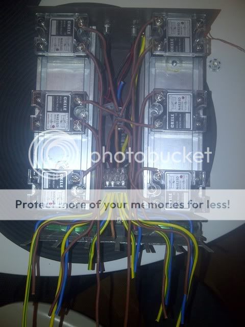
My distribution boards are made from IP rated steel enclosures with back plates, to which I have mounted din rails. The din rails will hold all my switch gear which will be a selection of SSRs, mechanical relays and contactors. I also have some proper din mount automation kit I am trying to hack the protocol for, but more on that later.

Here is a little tour of what I have done starting at the meter...


 photo WP_20131119_002.jpg


I got my energy provider to upgrade my meter tails between the main fuse on the left and meter with 25mm and I also got them to install an isolation switch for free :)


What this allows me to do is switch off the mains without pulling the main fuse myself (which you're not supposed to do). At the bottom you can see an adaptable box, this is where I split my meter tails after the isolation switch to 2x 16mm SWA cables. In the adaptable box is a 2x 5way Henley block which splits the live and neutral, there is also an earth block. A tip here is to make sure you get a big enough adaptable box, else you will waste hours like I did trying to bend and connect 16mm cable (not easy). This way you get a little extra room and slack to work.


The 2 armoured cables then go off to my 2 CUs (via a couple more adaptable boxes).


This is my main CU which will control the cellar, ground floor, central heating and garden.


 photo WP_20131119_004.jpg


The black box on the right is again another adaptable box, with SWA (armoured cable) you can't just stick it in to a plastic box like a consumer unit, instead you have to use a metal box so you don't crack what ever it is you are connecting it to. SWA is connected using a gland which is a bit like a hose pipe connector, it tightens on to the cable and allows you to connect the cable to something (in this case the adaptable box).


This then goes to the main switch on the CU which is spilt out to 2 RCDs which are the large modules you can see and they further split out to MCBs, which are the smaller modules you can see.


Evidently this doesn't look so neat at the moment and this is because it is still in a temporary layout whilst we test the connections throughout the house and whilst I get the distribution boards properly laid out.


As an example of how much I have going to this board, the mass of cables in the bottom right are the majority of the cables just for the cellar and ground floor. A tip here is make sure you mark your cables at both ends, else the connection process will become a nightmare!


There are a few cables which you might be able to see coming out of the MCBs and going down to the distribution board. These are my functional circuits such as ground floor lights, kitchen sockets, boiler, cooker, etc.


 photo WP_20131119_003.jpg

The distribution board is a little sparse and very messy at the moment, at the top you can see the earth commoned together. Below this is some 60A choc block which is currently connecting the kitchen sockets up. In the top right behind the mass of wires is the ground floor lights. The bottom left is a 24v PSU and a 40A relay I have been testing with above it. The white bar is some cable management trunking which will be present throughout once I finish. Finally the 2 MCBs at the bottom right are just being used temporarily to connect the ground floor sockets up.


This is by no way adhering to any electrical standards currently and is only in a format that should be used temporarily for testing.


Once finished I will have a rail that will distribute earth and neutral, the live will go to the supply side for each relay and each relay will have a live feed coming from the supply from the corresponding MCB and daisy chained between the relays.


It is important to physically isolate mains and low voltage, so all mains will run down the right hand side of the enclosure and the low voltage control signal will run down the left and no switching will leave the enclosure. This is really important because if anything went wrong you could end up with mains running through what you think is low voltage control gear. To enable this I will be using a netduino housed in the enclosure with a control board that will switch the relays using 24v. The netduino will be controlled wirelessly using a gainspan module and will be in a plastic box to physically isolate it. You could also use IR as an alternative, but the idea is to keep everything contained within the enclosure.

The control protocol is something I am still deciding on, whether I go the message based route using MQTT or if I implement RESTful services or standard GET POST methods.

I have been working on my database architecture quite intensively and have chosen a layered approach.

I wanted to have 2 separate databases to separate concerns such as audit/security and application data but be able to interface with the databases seamlessly using the same pattern.

My data layer is split in to:


- Data and helpers
- Contracts
- Ninject

Data contains the database definitions, UnitOfWork and Repositories. Within helpers I have RepositoryFactories, RepositoryProvider and IRepositoryProvider

Contracts contain IRepository and IUnitOfWork.

Ninject contains the IoC for my DAL.

I keep my models and enums separate so I can use them throughout all layers.

I then have a BusinessLogicLayer which contain all my application logic and I working on implementing workflows here.

Finally I am working on a service layer which will provide a point where all my applications can interface with my database.

My next task is to finalise my control boards for switching my relays. I have some ULN2008 which allow 24v to be controlled directly by a netduino.

Once this is in place I will be working on some netduino code to control these boards.

Stay tuned...

Monday, November 26, 2012

PCB - 3 Channel PWM LED Driver

I have been working for sometime on my LED drivers to enable me to have independent control of the 30 x 3W LEDs required to create various lighting effects for my aquarium lighting fixture.

Credit where its due, the design of this board is thanks to Magpie, my electronics knowledge is no where good enough to pull something this complicated off. I have spent a fair bit of time playing with the layout, learning how to use KiCad, understanding the circuit and selecting the correct parts for the board.

The board design has to address certain issues inherent with using PWM and the attributed noise it creates. To help combat this the board is laid out in a way that minimises track length between certain components and the use of what is known as Kelvin connections. The Kelvin connections are used to accurately measure current against the ground to get accurate readings.

The problem that can occur from poor design and layout (which I am yet to have any proof of until I test a board) are EM interference with other devises, flicker and inefficient power usage.

This board uses a micro with c code to very quickly take current readings and adjust the output value in order to maintain a stable and reliable output.

My first attempt is currently in production with Seeed so I expect to get my boards in the next few weeks. I have just ordered an Atten 858D+ rework station and am in the processes of ordering my components with digikey.

Here is a 3d view of the board design, the boards have 3 channels, each capable of supporting 1 3W Led and I will be using 10 of these boards.


Tuesday, October 23, 2012

Washing Up


Here's a little mix I did whilst I was meant to be washing up.

Enjoy!

Sunday, September 2, 2012

Netduino - Optocoupler testing

I have finally had chance to spend a few minutes on the last part of my relay control board, this part demonstrates the use of an optocoupler along with PWM to control a 12 volt LED. My next test will be to use this circuit with a computer fan in order to provide the fan control for my relay enclosure.

This circuit is very straight forward, it uses a 4N35M octocoupler, an LED and 2 resistors. There is a 1k resistor between the digital out of the netduino and pin 1 on the octo and another to match the LED. I am using a 12 volt 1 amp power supply in this example.


using System;
using System.Threading;
using Microsoft.SPOT;
using Microsoft.SPOT.Hardware;
using SecretLabs.NETMF.Hardware;
using SecretLabs.NETMF.Hardware.Netduino;

namespace CIRC_08
{
public class Program
{
static PWM pwm = new PWM(Pins.GPIO_PIN_D5);

public static void Main()
{
while (true)
{
for (int sensorValue = 1; sensorValue < 101; sensorValue++) { Debug.Print(sensorValue.ToString()); pwm.SetDutyCycle((uint)sensorValue); Thread.Sleep(100); } for (int sensorValue = 100; sensorValue > 2; sensorValue--)
{
Debug.Print(sensorValue.ToString());
pwm.SetDutyCycle((uint)sensorValue);
Thread.Sleep(100);
}

pwm.SetDutyCycle(0);
Thread.Sleep(10000);
}
}

}
}

Tuesday, June 26, 2012

Netduino - Update Relay Control Board Mock-Up

I have finally managed to get my relay control board prototype working. What this allows me to do is control the relays with 12 volts and also to light a 12v LED to display which relays are on.

I am currently using a 74HC595 to provide the control logic to switch the transistors on and off. The next stage is to control the fans using PWM, I also need to add a DS18B20 that will connect in to my 1-wire bus. The temperature sensor will be used to control the speed of the fans, I may in fact used 2 temperature sensors to control the 2 fans independently for each of the heat sinks.

As I now have a Netduino GO I am working towards modularising my main aquarium control board. The first thing I want to modularise is this control board so it will work with the GO bus. I am hoping that the STM8 will provide enough IO to control the transistors and also PWM for the 2 fans. It would also be amazing if there was a spare serial port so I can create a 1-wire bus on the same board, but I have a fair bit of learning to do before I can get started with the STM8S103F2P6 chips I've got.

Here is a little video showing the shift registers switching the transistors on and off that control the LEDs.


Sunday, June 24, 2012

Alpha Numeric Counter

Hi,

Here is a little Alpha numeric counter I have written that will either continue counting or will return the next value.


public string AlphaNum(string val)
        {
            StringBuilder sb = new StringBuilder(val);
            bool incNext = false;
            for (int n = sb.Length; n > 0; n--)
            {
                if (n == sb.Length || incNext)
                {
                    char nextChar;
                    char letter = Convert.ToChar(sb.ToString(n - 1, 1));
                    if (letter == '9')
                    {
                        incNext = true;
                        nextChar = 'A';
                    }
                    else if (letter == 'Z')
                    {
                        if (n - 2 > -1)
                        {
                            if (sb.ToString(n - 2, 1) != "Z")
                            {
                                incNext = true;
                                nextChar = '0';
                            }
                            else
                            {
                                incNext = true;
                                nextChar = 'Z';
                            }
                        }
                        else
                        {
                            incNext = true;
                            nextChar = 'Z';
                        }
                    }
                    else
                    {
                        nextChar = (char)(((int)letter) + 1);
                        incNext = false;
                    }
                    sb.Remove(n - 1, 1).Insert(n - 1, nextChar.ToString());
                }
            }
            return sb.ToString();
        }

Thursday, April 12, 2012

Netduino - Quick update...

I am still testing my aquarium control board, I have found a ground issue that is affecting the shift registers and in turn the TLC5940s. This is something that may take a while to solve and probably a lot of continuity testing and a bit of solder work.

My overall testing is going well at the moment, I have my shift register fully tested and working, bar the above ground issue. The realtime clock is working thanks to a little help from Stefan. Nevyn has lent my an oscilloscope while I find one, this has been great as I have started to learn how to use a scope and how to interpret the results which will be helpful for when I get one. The scope was a necessity in order to test the oscillator circuit and the TLCs PWM output. So far I have managed to find a few faults in the soldering of the oscillator and TLC circuits, I now have a square wave coming out of the oscilator, a saw tooth on the BLANK signal (which may need looking at) and I have managed to get an LED to light on the TLCs. Sadly this doesn't round of the testing of the TLCs and oscillator as the LED was kind of strobing along to the "Breath" code rather than smoothly diming in and out with a constant light. Again this may be related to the ground issue, but I have a feeling I need to further test the clock and BLANK signals.

BREAKING NEWS!!!

I have just ordered the new Netduino Go, the shield base and the touch screen display from Nwazet.

Can't wait!

Wednesday, March 28, 2012

Netduino - Prototype testing

This is just a quick update...

I am currently going through testing each part of my main control board to make sure it all works together. Hopefully all is well, but to make perfectly sure, despite some of my testing before I finished soldering everything up, I am going through every component again.

During the build I did a lot of continuity testing to make sure there were no broken tracks or joins that shouldn't exist. Powering the entire board didn't result in anything dramatic like smoke or fire, so I'm taking that as a good thing.

The main elements of the board to test in the initial phase are:

RTC
Shift Registers
TLCs

This covers the main functions and until all are working with code there’s no point moving on to the rest. I have most recently been trying out the TLC5940s for the first time. On first test with Nevyn's sample code nothing happened, on further investigation I remember that I delegated some of the logic for BLANK and VPRG to the multiplexed GPIOs, provided by the 74HC595s. I did a little bit of code reworking to incorporate Stefan's MultiSPI library and his shift register libraries and tried again. Unfortunately the code still failed and I think it is to do with the way I am trying to call the logic pins provided by the 595's. I will update further on this once I work out what is going wrong.

So far that’s 2 fails out of the 3, however thanks to some help from Stefan and no thanks to some confusion whilst soldering, I got the RTC back up and running.

Here is some sample code based on Fabien’s RTC library:


using System;
using System.Threading;
using Microsoft.SPOT;
using Microsoft.SPOT.Hardware;
using SecretLabs.NETMF.Hardware;
using SecretLabs.NETMF.Hardware.Netduino;
using netduino.helpers.Hardware;

namespace RTC
{
public class Program
{
public static void Main()
{
var clock = new DS1307();
DateTime CurrTime = DateTime.Now;
// Set the clock to some arbitrary date / time
clock.Set(CurrTime);

// Make sure the clock is running
clock.Halt(false);
while(true)
{
// Test reading RTC clock registers
Debug.Print(clock.Get().ToString());
Thread.Sleep(1000);
}

}
}
}


using System;
using Microsoft.SPOT;
using Microsoft.SPOT.Hardware;

namespace netduino.helpers.Hardware {
///


/// This class implements a complete driver for the Dallas Semiconductors / Maxim DS1307 I2C real-time clock: http://pdfserv.maxim-ic.com/en/ds/DS1307.pdf
///

public class DS1307 : IDisposable
{
[Flags]
// Defines the frequency of the signal on the SQW interrupt pin on the clock when enabled
public enum SQWFreq { SQW_1Hz, SQW_4kHz, SQW_8kHz, SQW_32kHz, SQW_OFF };

[Flags]
// Defines the logic level on the SQW pin when the frequency is disabled
public enum SQWDisabledOutputControl { Zero, One };

// Real time clock I2C address
public const int DS1307_I2C_ADDRESS = 0x68;
// I2C bus frequency for the clock
public const int DS1307_I2C_CLOCK_RATE_KHZ = 100;

// Allow 10ms timeouts on all I2C transactions
public const int DS1307_I2C_TRANSACTION_TIMEOUT_MS = 10;

// Start / End addresses of the date/time registers
public const byte DS1307_RTC_START_ADDRESS = 0x00;
public const byte DS1307_RTC_END_ADDRESS = 0x06;

// Square wave frequency generator register address
public const byte DS1307_SQUARE_WAVE_CTRL_REGISTER_ADDRESS = 0x07;

// Start / End addresses of the user RAM registers
public const byte DS1307_RAM_START_ADDRESS = 0x08;
public const byte DS1307_RAM_END_ADDRESS = 0x3f;

// Total size of the user RAM block
public const byte DS1307_RAM_SIZE = 56;

// Instance of the I2C clock
I2CDevice clock;

public DS1307() {
clock = new I2CDevice(new I2CDevice.Configuration(DS1307_I2C_ADDRESS, DS1307_I2C_CLOCK_RATE_KHZ));
}

///


/// Gets the date / time in 24 hour format.
///

/// A DateTime object
public DateTime Get() {
byte[] clockData = new byte [7];

// Read time registers (7 bytes from DS1307_RTC_START_ADDRESS)
var transaction = new I2CDevice.I2CTransaction[] {
I2CDevice.CreateWriteTransaction(new byte[] {DS1307_RTC_START_ADDRESS}),
I2CDevice.CreateReadTransaction(clockData)
};

if (clock.Execute(transaction, DS1307_I2C_TRANSACTION_TIMEOUT_MS) == 0) {
throw new Exception("I2C transaction failed");
}

Debug.Print(clockData[4].ToString() + "/" + clockData[5].ToString() + "/" + clockData[4].ToString());

return new DateTime(
BcdToDec(clockData[6]) + 2000, // year
BcdToDec(clockData[5]), // month
BcdToDec(clockData[4]), // day
BcdToDec(clockData[2] & 0x3f), // hours over 24 hours
BcdToDec(clockData[1]), // minutes
BcdToDec(clockData[0] & 0x7f) // seconds
);
}

///


/// Sets the time on the clock using the datetime object. Milliseconds are not used.
///

///
A DateTime object used to set the clockpublic void Set(DateTime dt) {
var transaction = new I2CDevice.I2CWriteTransaction[] {
I2CDevice.CreateWriteTransaction(new byte[] {
DS1307_RTC_START_ADDRESS,
DecToBcd(dt.Second),
DecToBcd(dt.Minute),
DecToBcd(dt.Hour),
DecToBcd((int)dt.DayOfWeek),
DecToBcd(dt.Day),
DecToBcd(dt.Month),
DecToBcd(dt.Year - 2000)} )
};

if (clock.Execute(transaction, DS1307_I2C_TRANSACTION_TIMEOUT_MS) == 0) {
throw new Exception("I2C write transaction failed");
}
}

///


/// Enables / Disables the square wave generation function of the clock.
/// Requires a pull-up resistor on the clock's SQW pin.
///

///
Desired frequency or disabled///
Logical level of output pin when the frequency is disabled (zero by default)public void SetSquareWave(SQWFreq Freq, SQWDisabledOutputControl OutCtrl = SQWDisabledOutputControl.Zero)
{
byte SqwCtrlReg = (byte) OutCtrl;

SqwCtrlReg <<= 3; // bit 7 defines the square wave output level when disabled // bit 6 & 5 are unused if (Freq != SQWFreq.SQW_OFF) { SqwCtrlReg |= 1; } SqwCtrlReg <<= 4; // bit 4 defines if the oscillator generating the square wave frequency is on or off. // bit 3 & 2 are unused SqwCtrlReg |= (byte) Freq; // bit 1 & 0 define the frequency of the square wave WriteRegister(DS1307_SQUARE_WAVE_CTRL_REGISTER_ADDRESS, SqwCtrlReg); } ///


/// Halts / Resumes the time-keeping function on the clock.
/// Calling this function preserves the value of the seconds register.
///

///
True: halt, False: resumepublic void Halt(bool halt) {
var seconds = this[DS1307_RTC_START_ADDRESS];

if (halt) {
seconds |= 0x80; // Set bit 7
}
else {
seconds &= 0x7f; // Reset bit 7
}

WriteRegister(DS1307_RTC_START_ADDRESS, seconds);
}

///


/// Writes to the clock's user RAM registers as a block
///

///
A byte buffer of size DS1307_RAM_SIZEpublic void SetRAM(byte[] buffer) {
if (buffer.Length != DS1307_RAM_SIZE) {
throw new ArgumentOutOfRangeException("Invalid buffer length");
}

// Allocate a new buffer large enough to include the RAM start address byte and the payload
var TrxBuffer = new byte[sizeof(byte) /*Address byte*/ + DS1307_RAM_SIZE];

// Set the RAM start address
TrxBuffer[0] = DS1307_RAM_START_ADDRESS;

// Copy the user buffer after the address
buffer.CopyTo(TrxBuffer, 1);

// Write to the clock's RAM
var transaction = new I2CDevice.I2CWriteTransaction[] {I2CDevice.CreateWriteTransaction(TrxBuffer)};

if (clock.Execute(transaction, DS1307_I2C_TRANSACTION_TIMEOUT_MS) == 0) {
throw new Exception("I2C write transaction failed");
}
}

///


/// Reads the clock's user RAM registers as a block.
///

/// A byte array of size DS1307_RAM_SIZE containing the user RAM data
public byte[] GetRAM() {
var ram = new byte[DS1307_RAM_SIZE];

var transaction = new I2CDevice.I2CTransaction[] {
I2CDevice.CreateWriteTransaction(new byte[] {DS1307_RAM_START_ADDRESS}),
I2CDevice.CreateReadTransaction(ram)
};

if (clock.Execute(transaction, DS1307_I2C_TRANSACTION_TIMEOUT_MS) == 0) {
throw new Exception("I2C transaction failed");
}

return ram;
}

///


/// Reads an arbitrary RTC or RAM register
///

///
Register address between 0x00 and 0x3f/// The value of the byte read at the address
public byte this[byte address] {
get {
if (address > DS1307_RAM_END_ADDRESS) {
throw new ArgumentOutOfRangeException("Invalid register address");
}

var value = new byte[1];

// Read the RAM register @ the address
var transaction = new I2CDevice.I2CTransaction[] {
I2CDevice.CreateWriteTransaction(new byte[] {address}),
I2CDevice.CreateReadTransaction(value)
};

if (clock.Execute(transaction, DS1307_I2C_TRANSACTION_TIMEOUT_MS) == 0) {
throw new Exception("I2C transaction failed");
}

return value[0];
}
}

///


/// Writes an arbitrary RTC or RAM register
///

///
Register address between 0x00 and 0x3f///
The value of the byte to write at that addresspublic void WriteRegister(byte address, byte val) {
if (address > DS1307_RAM_END_ADDRESS) {
throw new ArgumentOutOfRangeException("Invalid register address");
}

var transaction = new I2CDevice.I2CWriteTransaction[] {
I2CDevice.CreateWriteTransaction(new byte[] {address, (byte) val})
};

if (clock.Execute(transaction, DS1307_I2C_TRANSACTION_TIMEOUT_MS) == 0) {
throw new Exception("I2C write transaction failed");
}
}

///


/// Takes a Binary-Coded-Decimal value and returns it as an integer value
///

///
BCD encoded value/// An integer value
protected int BcdToDec(int val) {
return ((val / 16 * 10) + (val % 16));
}

///


/// Takes a Decimal value and converts it into a Binary-Coded-Decimal value
///

///
Value to be converted/// A BCD-encoded value
protected byte DecToBcd(int val) {
return (byte)((val / 10 * 16) + (val % 10));
}

///


/// Releases clock resources
///

public void Dispose() {
clock.Dispose();
}
}
}


The next group of things to test after I get the shift registers and TLCs working will be:

SD
Wi-Fi
Serial Mux
LCD
PH
1-Wire (Waiting on 4.2 release with 1-wire support)
Auto temp probe registering 1-wire network.

Thursday, March 22, 2012

Netduino - High Power LED drivers

I am currently working on a high power LED driver; this will be used to drive my aquarium lighting.

So a brief overall spec:

The aquarium lighting rig will allow for individual control of the LEDs, this will allow for lighting effects such as cloud cover, seasons, lunar/solar cycles and lightening.

These effects along with the overall lux, colour and contrast will be achieved by having control over the LEDs individually. There will be 3 watt white Cree's, Royal Blues, Red and Greens. This combination will allow for both day and moon light and the reds and greens will allow me to adjust the colour warmth.

In total there will be 30 Leds:

14 x 3W White Cree
10 x 3W Royal Blue
3 x 3W Red
3 x 3W Green

The LEDs will be mounted on a 3mm aluminium sheet, evenly spaced, with various lenses to create an even colour and lux distribution.

The LED drivers will need to be extremely efficient i.e. above 90%, the design Magpie is proposing should achieve over 95% efficiency when used with 6 LEDs in a chain. As I will be using only 1 LED per chain this will be slightly less efficient but I am hopeful that I will still achieve at least 90%.

I will give some more specific details about the drivers and the overall build as I have more information. Currently I have the LEDs and some inductors for building the drivers, so the next steps will be to get the rest of the parts I need and in the mean time I will be testing the TLC5940s which will be providing the PWM control for the LED drivers.

Wednesday, February 29, 2012

Netduino - Project Update

My prototype control board is now completely soldered up now.

I still need to do some testing, but I have powered it all up and it didn't set on fire, so I'm hoping all is well.

The main improvement is that the TLC59040s are fully soldered up.

I'm going to test all the various functions over the next month and will also be purchasing the various components I need for my LED drivers, relay enclosure and relay control board.

Here are a few pictures of the control board so far...


Wednesday, February 22, 2012

Relay Enclosure

I have been working on a relay enclosure for a little while, the main aims of this part of the project is to safely and to an electrical safe standard, design and build a high power relay enclosure.

The enclosure has been designed using 25amp SSR relays and 10amp rated IEC sockets. I have used 2.5 guage solid core cable and all of the IEC are fused, with the input one also having a switch.

For the low power control of the relays, I am currently designing a dip switch configurable option to choose whether transistors are normally open or normally closed for each channel. This will allow me to have a fail save for the various equipment that needs powering, even if the control board fails. For example heating and pumps will always need power, where as air pumps and lights may be less critical to life support.

Thermal management has been a key focus in the design of the relay enclosure, to take care of this aspect I have used a vented steel case, 2 large heat sinks and 2 pc fans. The temperature of each heat sink will be monitored using DS18B20 or similar temperature sensors on the 1-wire bus. The readings from these sensors will allow me to control fan speed and if necessary turn of relays if they are over heating.

The enclosure has 6 panel mounted LEDs at the front, this will indicate which relays are on, whilst fan speed will be displayed on the main controller LCD along with the temperatures. The 3.3v logic from the shift registers will be used to control transistors which will control the 12v supply that will be used to swith the relays. Whilst the 3.3v is enough to directly control the relays, I want to provide some isolation from the netduino and also take some of the power power burden of the netduino's regulators.

Below is a picture which shows my mains wiring, as you can see I am using the WAGO terminals to distribute the mains supply. I have cut all the IEC holes and have already set my switched, fused input socket, but am yet to order the 6x fused output sockets. All of the mains power is being kept at the top of the enclosure in the middle, this will be seperated with some blank pcb from the low power control board which will go at the bottom between the relays and will held keep the main away from the case should a connection become loose (which I can assure you it won't). Also the case itself will be earthed for added protection.


I will will post an update shortly once I have finished designing the control circuit.

Tuesday, December 27, 2011

Netduino - Long awaited update

Its been a long time since I posted anything, but my project has come a long way during this time...

Since my last post which was me drawing my schematic for a PCB to be printed, I have followed the advice of a few people over at the netduino forums (mainly mario and mark) and have nearly finished making a protoboard. I am getting on quite well, the schematic has changed a little here and there and I'm sure during testing and programming of my protoboard there will be even more changes and additions to come.

So far I have done the vast majority of soldering on my protoboard, I started with the layout, which I must say doesn't entirely represent my PCB layout, but I guess this is to test the circuit works as expected. I've got the RTC, the 595s and 165s completely soldered up and as you can see in the picture below, I have tested the shift registers and they are working perfectly!


I am really pleased with this, nothing has set on fire, gone bang or more disappointingly... done nothing! So this is a good start.

Next I am going to test that the RTC works and then I will be able to test the netduino pluged straight in to my protoboard without wire connecting specific things up. Once that is working I will finish off the LCD connection soldering and 4052 serial mux so I can select the LCD as a device. This will be the first time I have used the 4052 so it will be an interesting test, fingers crossed all will be well.

The osscilator for the tlc5940s is barely on the board yet, I have litterally just placed the chip holders, soldered some headers for the pwm outs and attached the power and grounds. I could really do with testing this on some breadboard first as I am still a little unsure as to how the osscilator needs connecting up.

Hopefully in my next post I should have a working clock, LCD and a soldered up osscilator!

P.S. Here is a top and bottom view of the board


Sunday, October 2, 2011

Netduino - Aquarium Schematic

Here is my first attempt at drawning a project schematic, I may still need to add an extra 74hc595 and there needs to be 2 daisy chained tlc5490's for pwm control.