I have been working on a relay enclosure for a little while, the main aims of this part of the project is to safely and to an electrical safe standard, design and build a high power relay enclosure.
The enclosure has been designed using 25amp SSR relays and 10amp rated IEC sockets. I have used 2.5 guage solid core cable and all of the IEC are fused, with the input one also having a switch.
For the low power control of the relays, I am currently designing a dip switch configurable option to choose whether transistors are normally open or normally closed for each channel. This will allow me to have a fail save for the various equipment that needs powering, even if the control board fails. For example heating and pumps will always need power, where as air pumps and lights may be less critical to life support.
Thermal management has been a key focus in the design of the relay enclosure, to take care of this aspect I have used a vented steel case, 2 large heat sinks and 2 pc fans. The temperature of each heat sink will be monitored using DS18B20 or similar temperature sensors on the 1-wire bus. The readings from these sensors will allow me to control fan speed and if necessary turn of relays if they are over heating.
The enclosure has 6 panel mounted LEDs at the front, this will indicate which relays are on, whilst fan speed will be displayed on the main controller LCD along with the temperatures. The 3.3v logic from the shift registers will be used to control transistors which will control the 12v supply that will be used to swith the relays. Whilst the 3.3v is enough to directly control the relays, I want to provide some isolation from the netduino and also take some of the power power burden of the netduino's regulators.
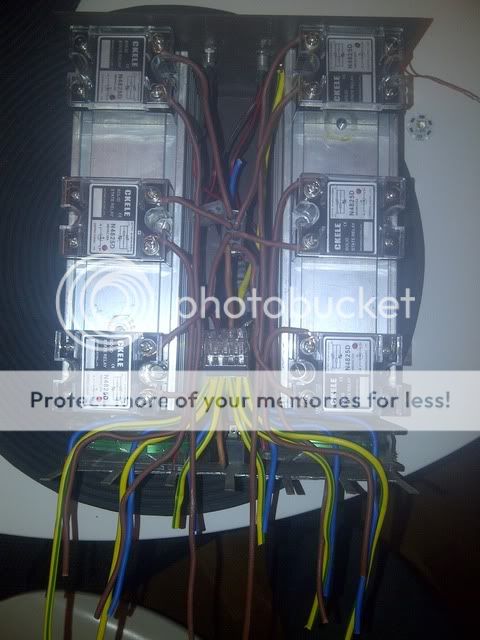
Below is a picture which shows my mains wiring, as you can see I am using the WAGO terminals to distribute the mains supply. I have cut all the IEC holes and have already set my switched, fused input socket, but am yet to order the 6x fused output sockets. All of the mains power is being kept at the top of the enclosure in the middle, this will be seperated with some blank pcb from the low power control board which will go at the bottom between the relays and will held keep the main away from the case should a connection become loose (which I can assure you it won't). Also the case itself will be earthed for added protection.
I will will post an update shortly once I have finished designing the control circuit.